How photogrammetry works: structure from motion, step by step
How structure from motion finds the same points in hundreds of photos, works out where every camera was, builds a point cloud and a mesh, and lays an orthomosaic and elevation model over the ground.
Published · 11 min read · By Malya, the makers of Clarity
A pile of photographs goes in; a model you can measure comes out. In between is a chain of steps that every photogrammetry program runs in roughly the same order, whatever it calls them. This page walks the chain with the pictures from a real survey, the demo quarry every Clarity account carries, so each step is shown on the data it actually produced.
The pipeline, with the real pictures
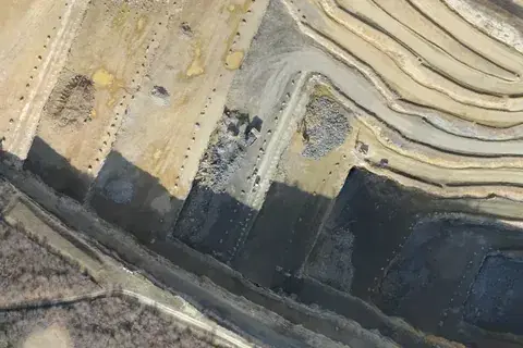
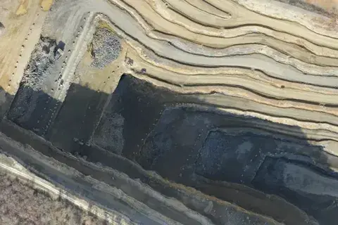
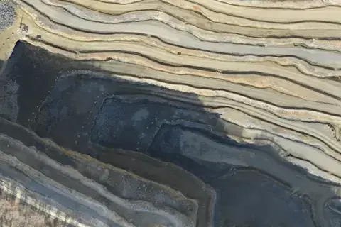
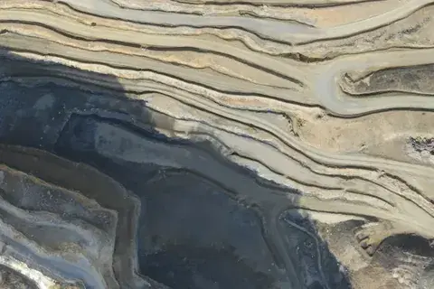
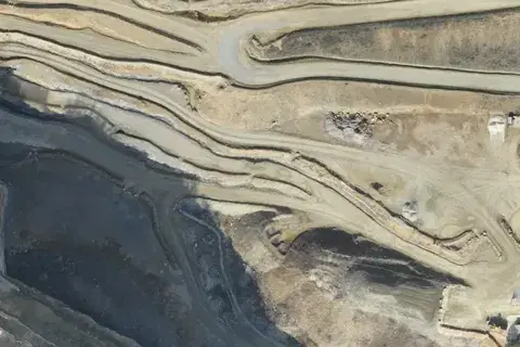
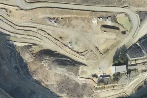
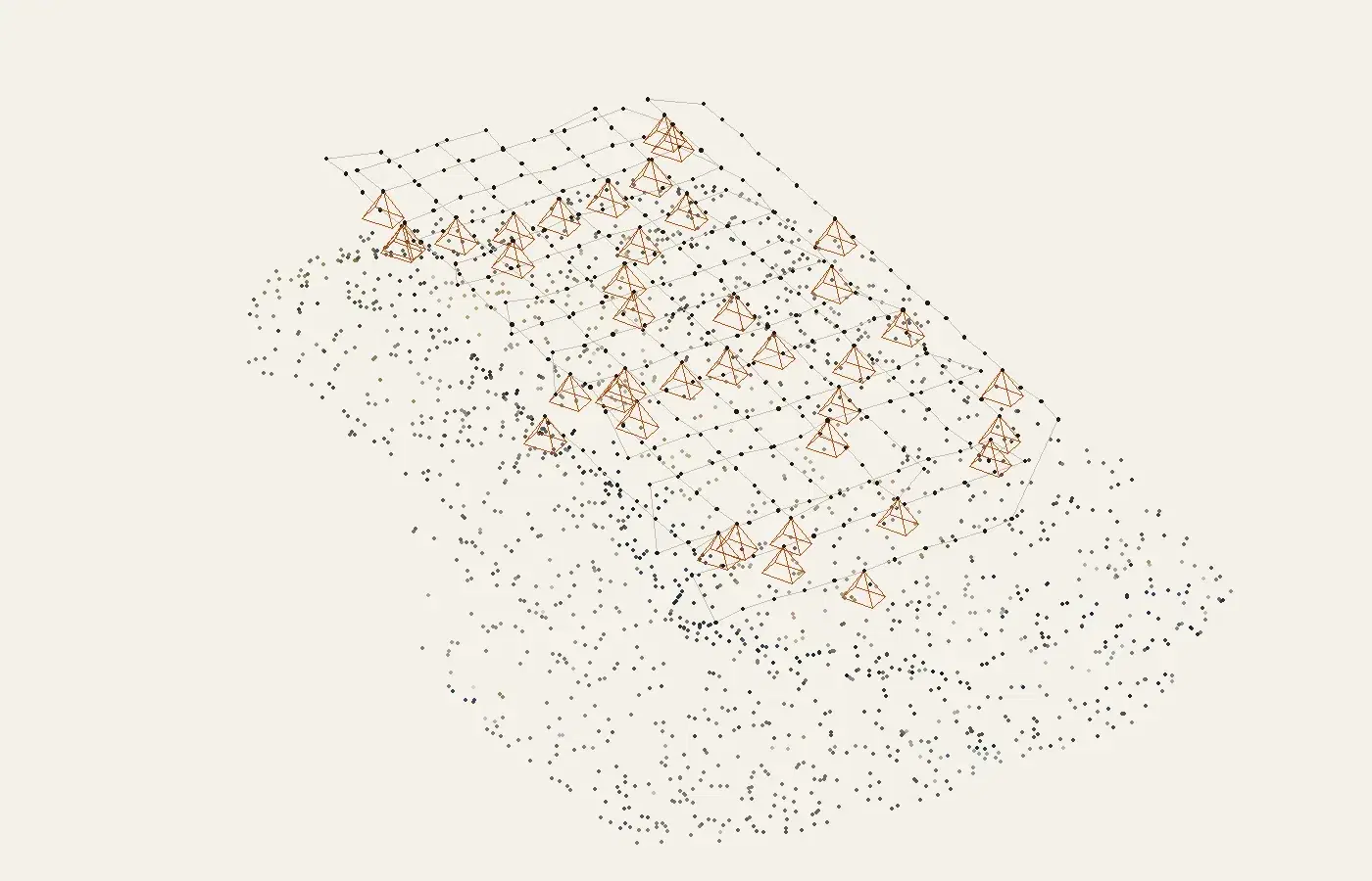
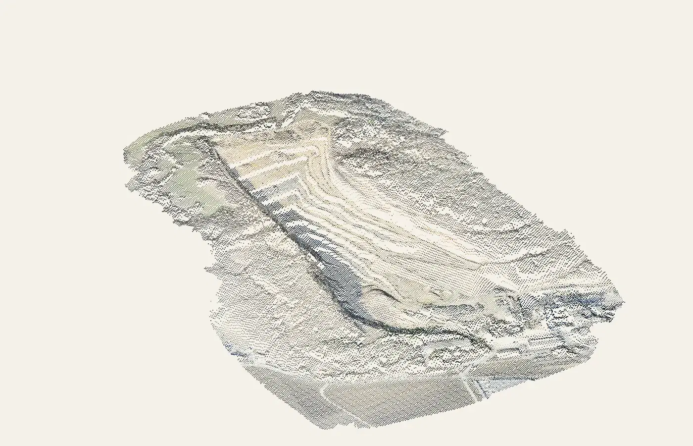
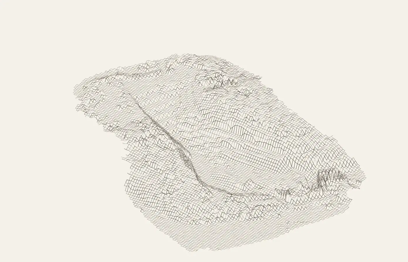
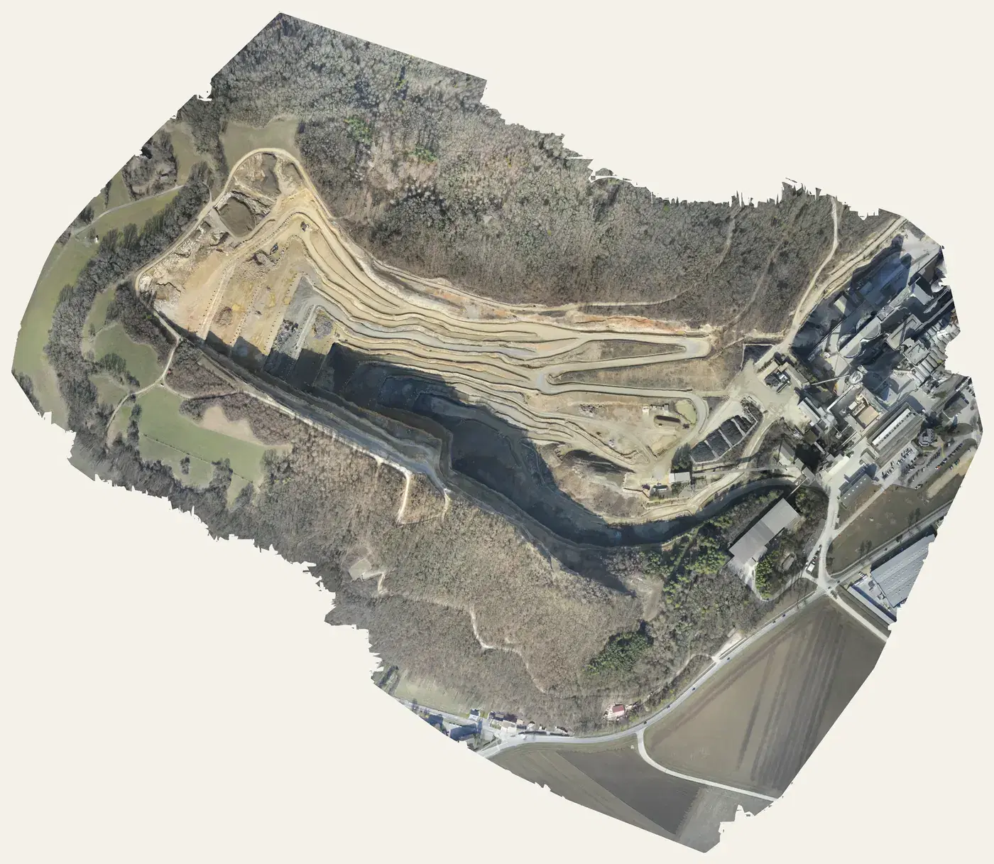
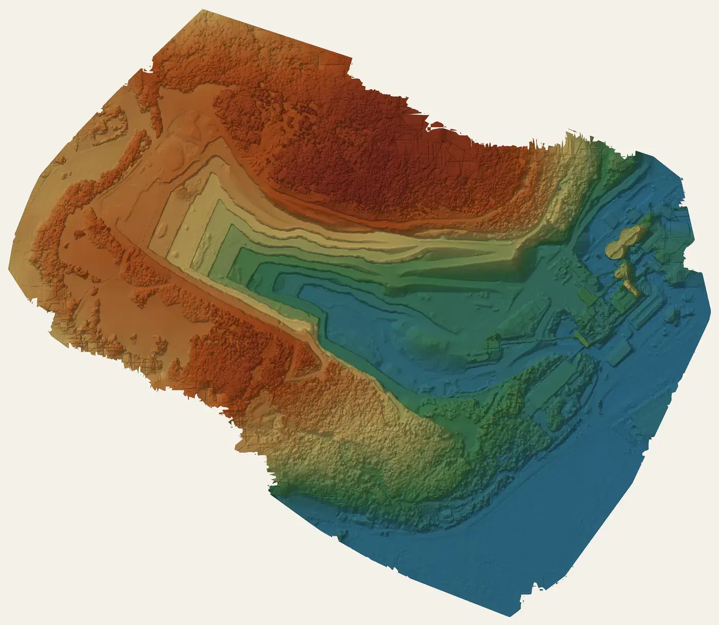
Step 1 of 8
Photographs, overlapping
The drone flies lines over the site, taking a photo every few seconds so that each point on the ground is in many pictures: typically 75% overlap along a line and 65% between lines.
Worth knowing
Every photo also records where the camera roughly was (GNSS) and, on better drones, to a few centimetres (RTK).
Structure from motion: finding and matching features
The software cannot be told “this stone here is that stone there”; it has to find out. It starts by looking through every photograph for small patches that are distinctive enough to be recognised again from a different angle and distance: corners, specks, the edges of stones, the ends of tyre marks. Each one is described by the pattern of brightness around it in a way that does not change much when the picture is rotated, scaled or lit differently. A good photograph yields tens of thousands.
Then the descriptions are compared between photographs that could overlap. Where the same patch is found in two or more pictures it becomes a tie point: one spot in the world, with a pixel position in each picture it appears in. Thousands of wrong matches are proposed and thrown out, because a true tie point must sit on a consistent line of sight from every camera that saw it, and a false one will not.
Bundle adjustment: everything at once
With tens of thousands of tie points, each seen from several cameras, the software has a huge set of small facts: “point 4,812 appears at pixel (2,310, 1,044) in photo 17 and at (1,980, 1,102) in photo 18”, and so on. The unknowns are where every camera was and which way it pointed (six numbers per photograph), the lens’s own geometry (focal length, the exact centre, and how it bends straight lines towards the edges), and the position in space of every tie point.
Bundle adjustment solves for all of them together, adjusting every number a little at a time until the disagreement in every photograph is as small as it can be: that is, until the solved point, projected back through the solved camera, lands as close as possible to the pixel where it was actually seen. The remaining disagreement is the reprojection error, measured in pixels, and a few tenths of a pixel is a good result. The “bundle” is the bundle of light rays through each camera.
- base / height
- 0.28
- position error
- ≈ 3 cm
- height error
- ≈ 11 cm
The result is a sparse cloud of tie points in three dimensions and a camera at every photograph, each with its position and orientation. The drone’s own GNSS record of where it took each picture goes in as a starting guess; if the drone has RTK, it goes in as a strong constraint. Ground control points enter here too, and pin the free-floating block to the ground.
From sparse to dense
Tens of thousands of points are enough to fix the cameras but not to describe a quarry. With the cameras known, the search for depth can be run at nearly every pixel: for a pixel in one photograph, the matching pixel in a neighbouring photograph must lie along one known line, so the software slides a small window along that line and picks the best agreement. Repeated across the overlap of every pair of photographs, and cross-checked between them, this produces a depth map per picture and, merged, a dense point cloud: millions of points, each coloured from the photographs it came from.
Resolution now follows the pixel size on the ground: a survey flown at a 2 cm GSD gives points a few centimetres apart. Trees, water and glass are where the depth search goes wrong, for the same reason the feature matcher struggled: there is nothing stable to compare.
Mesh, orthomosaic, elevation
The products are all made from the dense cloud, so they agree with one another.
- Mesh
- Points joined into triangles, the photographs projected onto them as texture. The 3D model you orbit.
- Digital surface model
- The surface sampled onto a grid of heights: everything the camera saw, including trucks, canopy and stockpiles.
- Digital terrain model
- The same grid with vegetation and objects classified out, so it is the ground. Cut and fill, contours and grading come from it.
- Orthomosaic
- Each photograph re-projected onto the surface and down into a map view, then blended: one image, straight down, at constant scale.
The orthomosaic deserves a word, because people measure on it most. A plain aerial photograph is taken from one point, so tall things lean away from the centre and the scale changes across the frame. The ortho correction uses the surface model to put every pixel where it would be if seen from directly above, which is why an orthomosaic can be measured for position, length and area like a map. It cannot be measured for height, because it has none: software that reads a height off an orthomosaic is reading the elevation model underneath.
Scale and coordinates
Nothing in a photograph says how big anything is. A block of photographs solved on its own is correct in shape and arbitrary in scale, position and orientation; it has to be tied to the world. There are three ways, used alone or together.
From the cameras
- The drone records where each photograph was taken. Plain GNSS puts that within a metre or two; RTK or PPK within a few centimetres.
- Hundreds of positioned cameras fix scale and position well horizontally.
- With nadir-only photographs the height can still drift: published checks show vertical error ten or twenty times the pixel with RTK alone, down to a few pixels with oblique photographs added.
From the ground
- Ground control points: surveyed targets laid out before the flight and clicked in the photographs afterwards.
- Pin the block to real coordinates and take out any bend in it. The most effective thing for vertical accuracy.
- In close-range work, scale bars of known length do the same job without a coordinate system.
Whichever way, the honest measure of the result is a set of check points: surveyed positions not used in the solution, compared with the model afterwards. The accuracy page has the published figures.
What goes wrong, and where
Each step has its own failure, and knowing which step failed is most of the diagnosis.
- Too few features
- Blank surfaces, blur, over- or under-exposure. Holes in the model, or whole photographs left out.
- Weak geometry
- Too little overlap, all photographs nadir at one height, a long thin corridor. The block bends: the dome effect.
- Bad lens model
- A lens that changed focus or zoom between shots, or a rolling shutter at speed. Systematic error that no amount of control removes.
- Nothing to tie to
- No control, no RTK, no scale bar. A good-looking model that measures wrong, or sits in the wrong place.
The limitations page takes each of these in turn, with its cause and its fix, and the 101 is the practical version: how to plan and fly so that none of them happen. The same chain on a drone survey, from the flight to the measured map, is in the aerial photogrammetry guide; to have it run on your own photographs, Clarity’s drone image processing.
Sources
Questions people ask
How does software know where the photos were taken?
It does not need to be told. From the same features seen in many photographs it solves the camera positions and the points together, in one calculation called bundle adjustment. The drone's own GNSS record is used as a starting guess and, if it is RTK, as a strong constraint.
What is structure from motion?
The modern form of the method: features are found in every picture, matched between pictures, and the cameras and 3D points are solved from the matches with no prior knowledge of where the camera was. The 'motion' is the camera moving between shots; the 'structure' is the scene.
Why does it need so much overlap?
A point must be in at least two photographs to be placed at all, and in several for the placement to be strong. Overlap of 75% along a line and 65% between lines puts each point in roughly nine pictures, which is what makes the solution rigid and the height reliable.
How long does photogrammetry processing take?
From minutes for a few dozen photographs to many hours for several thousand at full resolution. Feature matching and dense matching are the slow steps; the bundle adjustment itself is fast. Cloud processing runs it on machines sized for the job.
Where does the scale come from?
Nothing in a photograph says how big anything is, so scale comes from outside: the positions of the cameras (GNSS, ideally RTK), surveyed targets on the ground, or a bar of known length in the pictures. Without one of these the model is correct in shape and arbitrary in size.
See it on a real site.
Explore is free, with no card and no expiry: a real quarry, already flown and processed, with every measuring tool on it.
Read next
- Photogrammetry 101: how to make a 3D model from photosPlan, capture, control, process, check, deliver: the whole job, with the numbers to plan it by.
- What is photogrammetry? Definition, history and usesThe science of measuring from pictures: the idea, the history, and what a survey comes back as.
- Types of photogrammetry: aerial, close-range, satellite and moreAerial, close-range, satellite, underwater; stereo and structure from motion; which fits which job.
- All resources