Cut and fill from a drone survey, against your design
Bring the surface your engineer exported, as LandXML or DXF. Clarity sets the ground you flew against it and reports cut, fill and net for any area you draw.
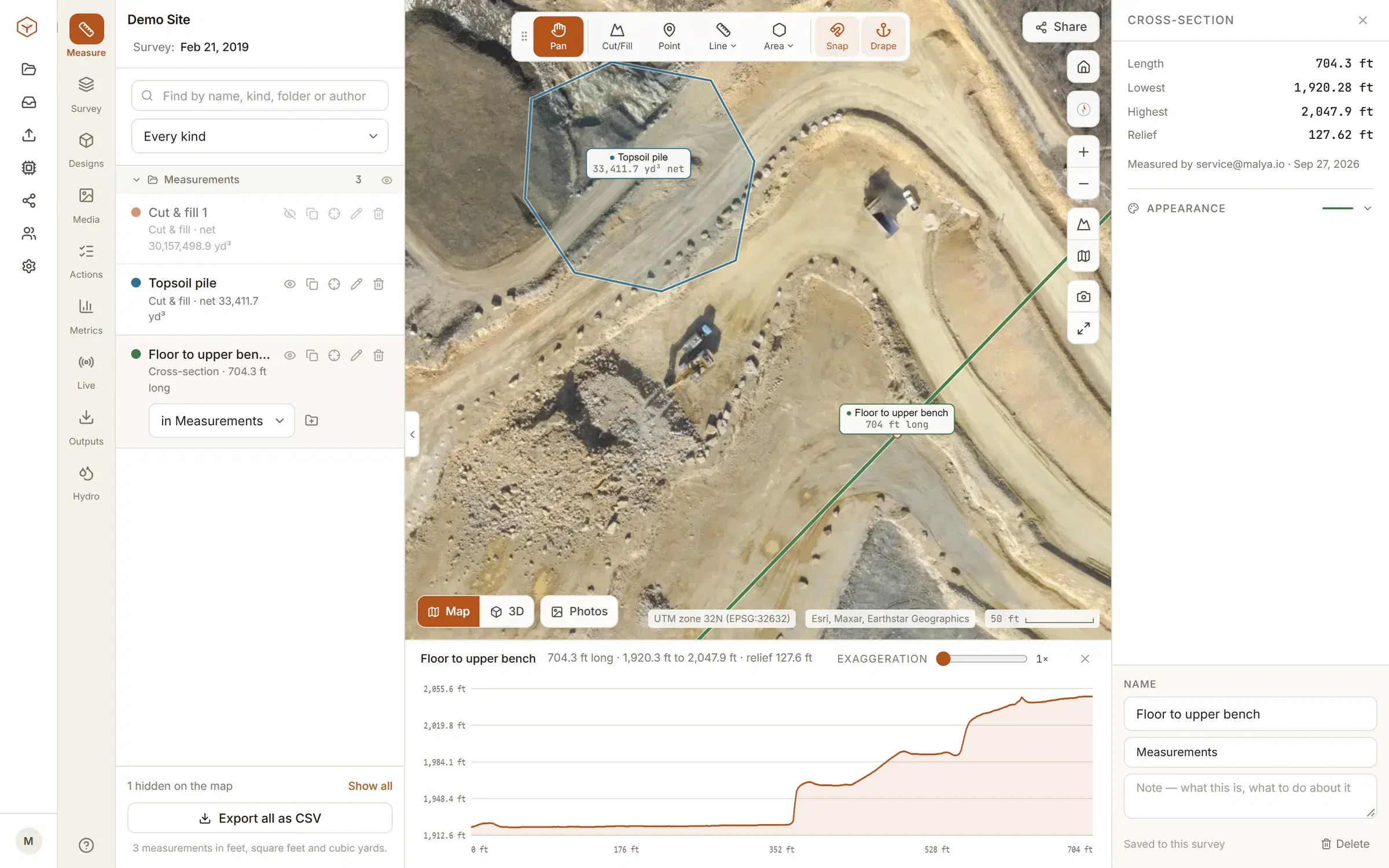
What the ground is measured against.
Cut and fill is the height between two surfaces, added up over an area. One surface is the terrain model from the flight. The other is yours to pick, and it is shown with the result.
- A design surface
- LandXML or DXF. Cut is ground standing above the design; fill is what it would take to bring the ground up to it.
- An earlier flight
- Another flight of the same site. Ground that is now higher counts as fill; ground that has dropped counts as cut.
- Levels you type in
- One fixed level, or a level at each corner of the boundary with the surface interpolated between them: a pad, a bench, a cell floor.
- The ground itself
- The lowest, highest or mean point inside, or a best-fit plane, when there is no design behind the job. That is how a stockpile is measured.
Bring the design in as LandXML or DXF.
Drop the file your engineer exported onto a flight. Every cut and fill boundary on that flight can then be measured against it, and a difference map runs against it too.
Four things about the file are worth knowing before you ask for it.
- A DXF has to be a real surface, made of 3D faces or a polyface mesh, and saved as ASCII. A drawing of contour lines is not one.
- A DXF is read as metres, so ask for it in metres.
- The design has to be in the same coordinate system as the site, and that has to be a WGS84 UTM zone. Clarity tells you which system the site is in.
- The file can be up to 150 MB.
A design rarely covers the whole site. Where it reaches only part of the boundary you drew, the result gives the area that was actually measured, rather than quoting a volume as if it covered all of it.
Uploading a design surface is part of Studio: $50 a month for up to five sites, with no charge per person. Studio starts from the orthomosaic and terrain models you have already processed, as GeoTIFFs. It does not process raw photos; that is Enterprise. What each plan includes.
Between two flights, the earlier one is the design.
Fly the same site twice and the first flight becomes a base like any other. That is how progress is tracked: the same measurement, repeated on a later date. It needs the two flights on the same heights, which means ground control or RTK each time. Difference two flights, or measure one against the other, and where they stand more than about half a metre apart as a whole Clarity says so beside the result.
What moved
Difference two flights into a map of where the ground rose and where it fell, with cut, fill and net. The larger patches of ground that moved are listed separately, each with its own volume.
Deadband
Two surveys of ground nobody touched never agree exactly. Height differences smaller than the figure you set are ignored, so survey noise is not counted as movement.
Swell and shrink
A factor on the cut and a factor on the fill, for material that bulks when it is dug and tightens when it is placed. A density turns either into tonnes.
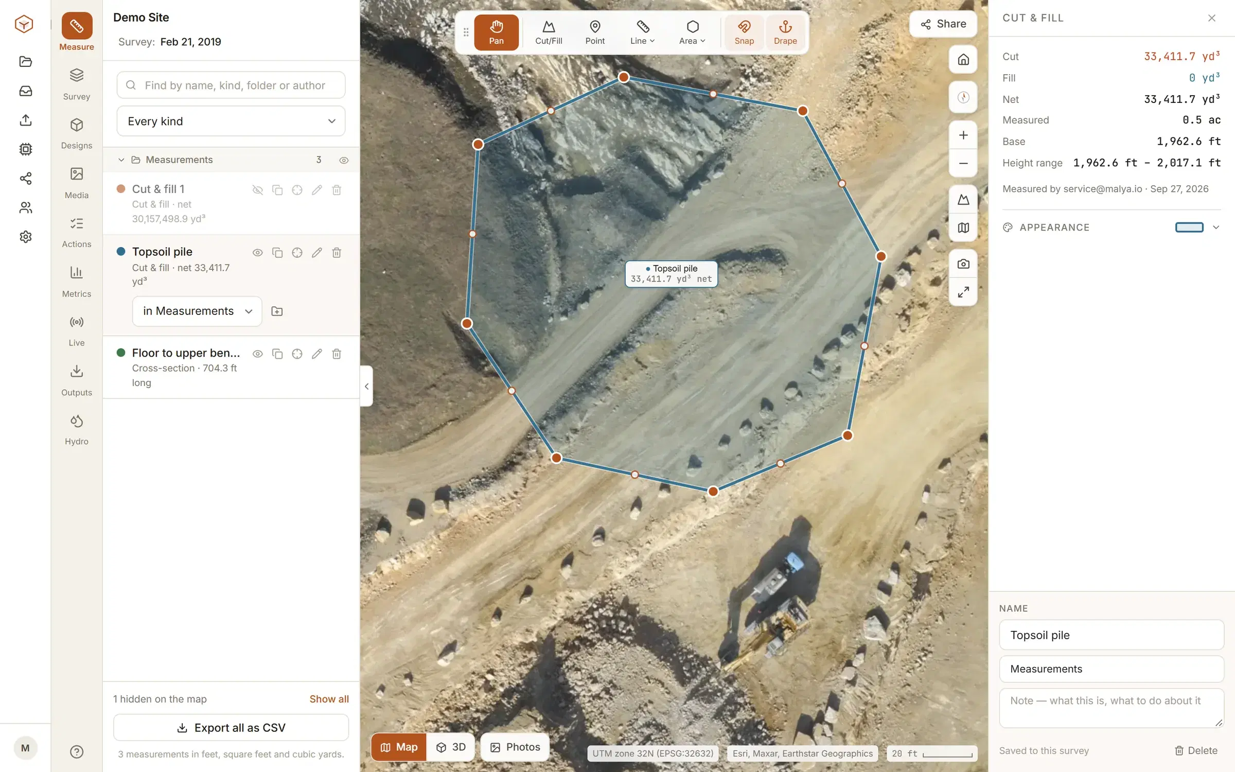
A result you can check, and a section through it.
Cut, fill and net are reported separately, with the area measured, the base and the height range beside them.
When a volume looks wrong, the quickest check is a line across it. Draw a cross-section anywhere and read the ground along it: its length, lowest point, highest point and relief, with the profile drawn under the map. Click two points on the profile for the grade between them.
Contours, slope colouring and the rest are under Tools. Cut and fill from cross-section areas you already have: the cut and fill calculator.
Back to the people who drew the design.
Quantities are no use in a browser tab. They leave in the formats a civil package opens.
- Measurements
- CSV, GeoJSON, DXF
- Flown surface
- LandXML
- Contours
- DXF at true elevation
- Report
- A page you print to PDF
DXF and LandXML files are drawn in the site’s UTM zone, and Clarity tells you which when the file saves, so nothing arrives floating at the origin. GeoJSON is in longitude and latitude. Everything that can be exported.
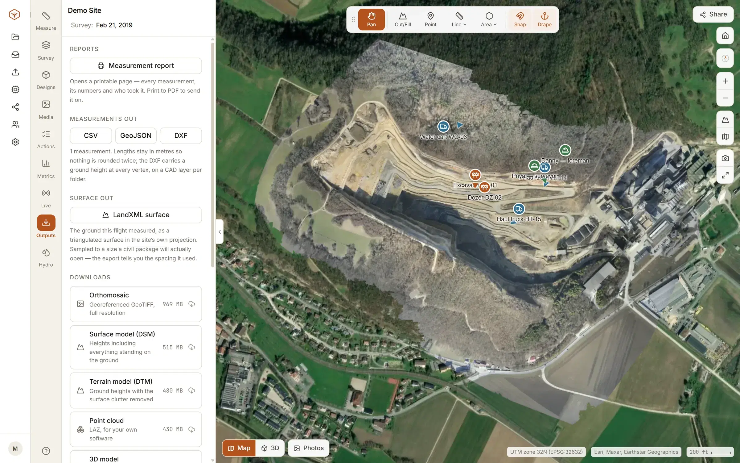
Try the tool on the demo quarry first.
Cut and fill works on the demo site on Explore, free. Your own design and your own flights are Studio, at $50 a month. See pricing.