Contour lines from a drone survey, at the interval you choose
Switch contours on and Clarity traces them in the browser from the terrain model of the flight. Read slope, relief and height off the same surface, then take the lines out as DXF at true elevation for the CAD package.
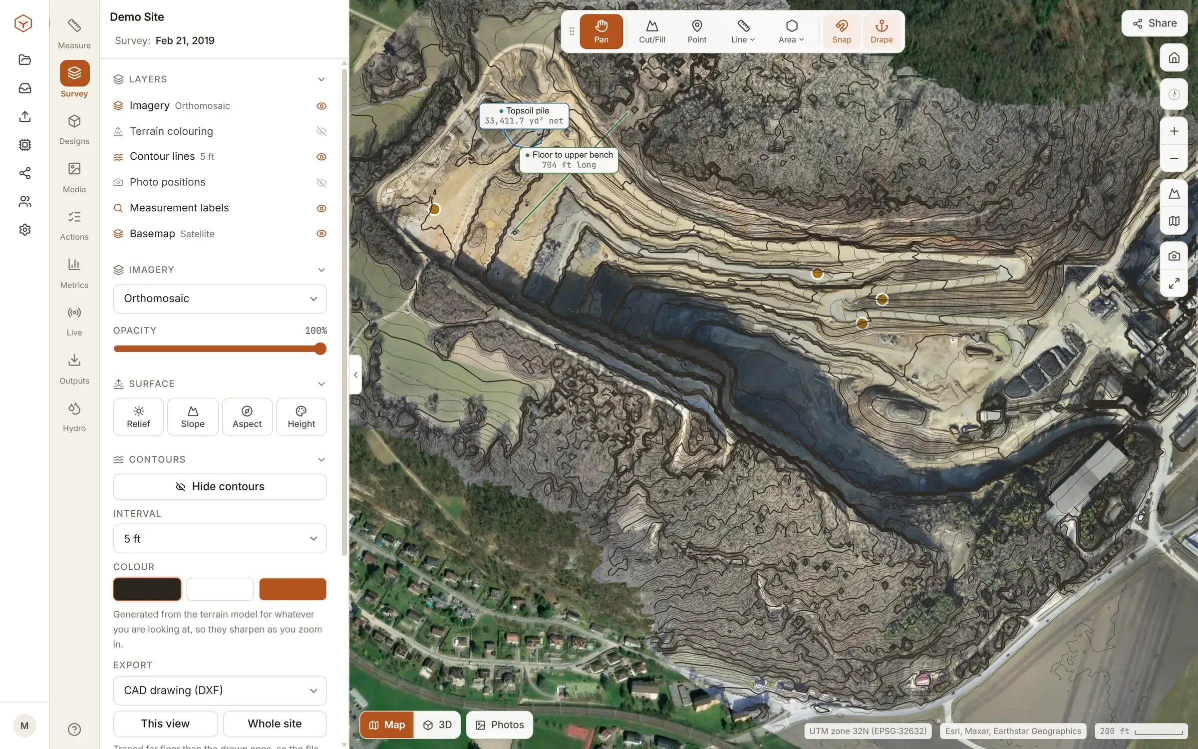
How the lines are drawn.
Contours are traced from the terrain model for whatever part of the site is on screen. Move the map and they are traced again, so they sharpen as you zoom in.
The lines on the map carry no height labels. For a level, the bar under the map reads the position and height under the pointer, and the Point tool drops a spot height you can keep.
- The interval
- Six steps, in the units the site is worked in: 0.25, 0.5, 1, 2, 5 or 10 metres, or 1, 2, 5, 10, 25 or 50 feet.
- Index lines
- Every fifth line is drawn heavier, so a face can be counted without following each line round.
- Colour
- Dark, light or the accent, whichever reads against the ground under it.
- One area on its own
- The Contours tool takes a boundary in place of the view. Click round a pad or a bench and the lines for that patch are saved to the flight as a measurement.
The lines follow the surface that was flown.
A contour is only as good as the model under it. It is the same terrain a stockpile volume is measured on, and it has the same limits.
Three things are worth knowing before a drawing goes to an engineer.
- The terrain comes from the surface model, which holds everything that stood on the ground on the day. Trees, buildings and parked machines get lines round them like any other shape.
- The lines stop where the model stops. A flight is rarely a neat rectangle, and no ground is invented past its edge.
- There is no smoothing pass. A rough surface gives rough lines, and a fine interval on flat ground shows the grain of the survey as much as the shape of the site.
How good the model is comes down to the flight: its resolution, its overlap and whether you used ground control.
Contours need a surface model. On Studio that means uploading it with the orthomosaic. An orthomosaic on its own gives the image only, with no terrain under it and nothing to contour. Which files to upload.
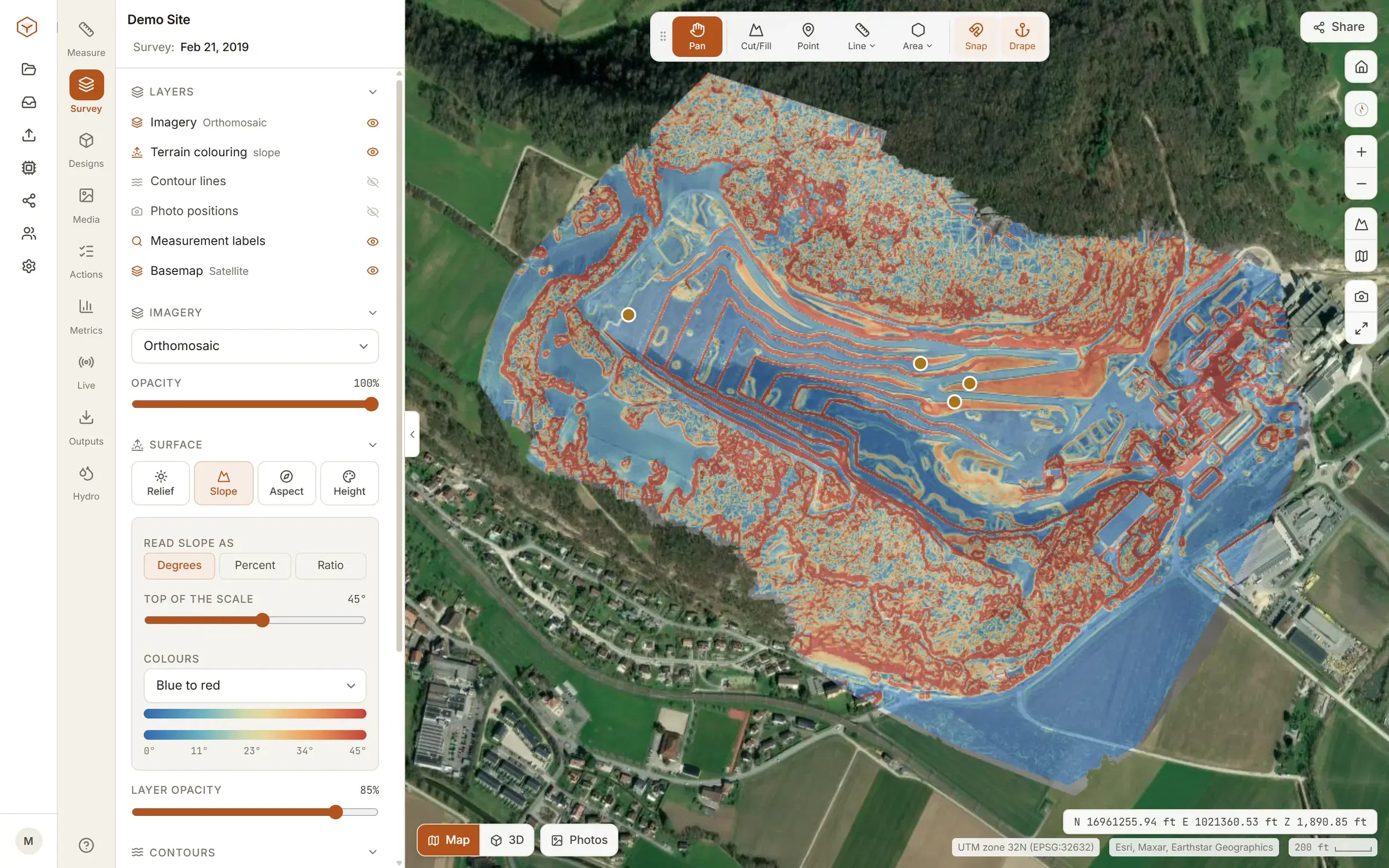
Slope, relief, aspect and height, off the same surface.
Contours are one way to read ground. The Surface panel has four more, each drawn over the imagery at an opacity you set.
- Slope
- How steep each piece of ground is, read in degrees, percent or as a ratio. Set the top of the scale to the steepest grade you are allowed to build and anything over it shows in the top colour.
- Relief
- Shading from a sun you can move round the compass and up and down the sky. A low sun brings out the benches, windrows and scours that a vertical photo flattens. Heights can be exaggerated for the shading; slope is always read from the true surface.
- Aspect
- Which way the ground faces, coloured round the compass. Ground flatter than two degrees is left clear, because an aspect for flat ground is noise.
- Height
- Height as colour between two levels. Let it follow the ground in view, or pin the levels so the colours mean the same on every flight of the site.
The colouring is for reading in the viewer, not a file to export. For a number in place of a picture, the Grade tool gives the rise, run and grade between two clicks, and a cross-section gives the profile along a line. Both are under Tools.
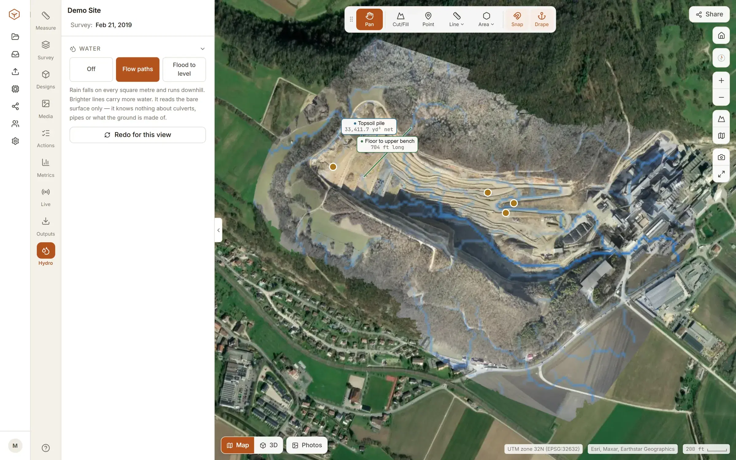
Where the water would run.
The Hydro tab reads the same surface for two quick answers about water. Both describe the shape of the ground and nothing else.
- Flow paths
- Rain is put on every part of the view and run downhill, with hollows filled first so a stream does not stop at the first dip. Brighter lines carry more water. It knows nothing about culverts, pipes or what the ground is made of.
- Flood to level
- Set a water level and everything below it is filled, with the area under water, the volume held and the deepest point. Low ground fills whether or not water could reach it: right for a pit or a pond, optimistic across open ground.
Both are worked out for the view on screen. Move the map and run them again.
Out as DXF, at true elevation.
Choose DXF in the Contours panel and export the view on screen or the whole site. Each line is a 3D polyline sitting at its own level, traced again for the file on a finer grid than the lines on screen.
- Geometry
- 3D polylines
- Layers
- CONTOUR_MAJOR, CONTOUR_MINOR
- Coordinates
- UTM zone of the site, in metres
- Extent
- This view, or the whole site
- Format
- R12 ASCII DXF
- Or as
- GeoJSON, in longitude and latitude
What is worth telling the engineer before the file is opened.
- Every fifth line goes on the major layer, so index and intermediate contours can be given different weights in the drawing.
- The drawing is in metres throughout: eastings, northings and elevations. That holds when the site is worked in feet too, so a five foot interval arrives as lines 1.524 m apart.
- Clarity names the UTM zone as the file saves. Where a flight was recorded in a system it cannot write, such as NAD83 UTM or a national grid, the drawing is made in the WGS84 UTM zone the site sits in, and the message says so.
- There is no text in the file. The height of a line is its elevation, not a label beside it.
- Both extents are sampled to the same number of points, so the view of one bench carries more detail than the whole site does. A very fine interval over deep ground is turned down, with a message asking for a coarser one.
We check the export by reading the file back with a separate DXF library. Drawing contours is free on the demo site; taking the file out is part of Studio and Enterprise.
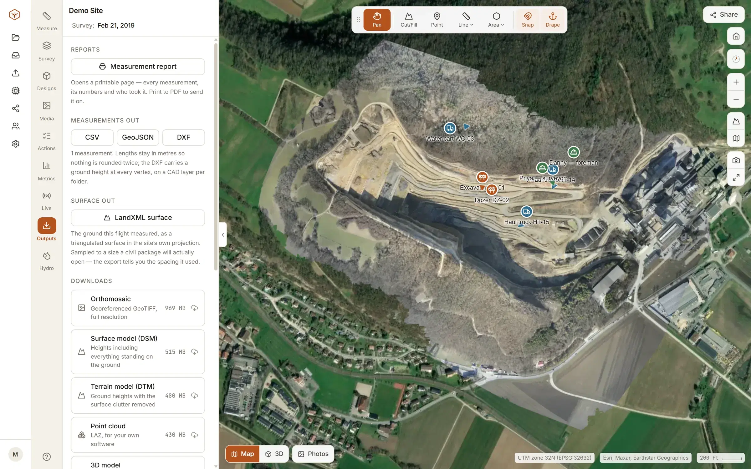
Or send the surface, and let them draw their own.
Some engineers would sooner have the ground than someone else’s lines. It leaves as a LandXML surface, or as the terrain models themselves.
The LandXML export is the ground as a triangulated surface, sampled to a size a civil package will open, and it tells you the spacing it used. Where the flight had no ground the surface has a hole, not an invented triangle.
The surface model downloads as a GeoTIFF, and so does the bare-earth terrain model where the flight has one. If the ground is going to be set against a design, that can be done here as well: cut and fill against a design surface.
Exports and downloads are part of Studio: $50 a month for up to five sites, with no charge per person. Studio starts from the GeoTIFFs you have already processed. It does not process raw photos; that is Enterprise, where we do. What each plan includes, and everything that can be exported.
Draw contours on the demo quarry first.
Contours, slope and the water tools work on the demo site on Explore, free. Exports and your own ground are Studio, at $50 a month. See pricing.